

split phase induction motor diagram
Types of 3 Phase Induction Motor. alaska artists paintings for sale. I Run is the current in the main winding and I Start is the current in the starting winding. 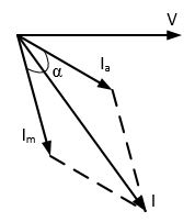 These motors have higher starting as well as running torque. single phase induction motor is not self-starting because the produced stator flux is alternating in nature and at the starting, the two components of this flux cancel each other and hence there is no net torque. It is a type of polyphase system employing three wires (or four including an optional neutral return wire) and is the most common method used by electrical grids worldwide to transfer power.. Three-phase electrical power was Reversing schematic. This block models four types of single-phase induction machines: Split-phase. CAPACITOR-START, INDUCTION-RUN MOTOR.
  Following diagrams is fairly simple, but making use of it inside the scope of how the device operates is a new different matter. The two currents are 1.
The induced voltage in the rotor is the result of magnetic induction, and then the magnetic field produced around the rotor.This field is opposite to the stator field (Len `z Law). Diagram DD6 Diagram DD8 M 1~ LN E Diagram DD9 M 1~ LN E White Brown Blue L1 L2 N S/C some standard frame induction motor diagrams have been included for ease of presentation. I have this motor from a DAIKIN Split type AC with the model of FTKC35PVM. Three-phase motors are a type of AC motor that is a specific example of a polyphase motor. a split-phase motor causes the auxiliary winding current to be shifted in time ahead of the running winding current to achieve magnetic field rotation during starting. Draw a schematic diagram of this split-phase induction motor connected for a 230-volt operation. A permanent split capacitor (PSC) motor is a type of single-phase induction motor. Once started the auxiliary winding is optional. One is the main and. Capacitor-start. Figure: Split-phase induction motor (a) Circuit diagram (b) Phasor diagram. The rotating magnetic field produced in the stator will create flux in the rotor, hence causing the rotor to rotate. The good thing is that you can get a 230V single phase supply from a three phase meter load points. Three Phase Induction Motor (3-ph I.M.) Draw the circuit and phasor diagram for motor. Split Phase Induction motor. Typically they can have up-to four times as much starting torque than a split-phase motor and are used on applications such as compressors, pressure washers and any small device requiring high starting torques. In this motor, starting winding has a capacitor in series with it. Due to the increased value of "", the starting torque of this motor is higher than that of the split-phase induction motor.
This article will take a closer look at a type of single-phase induction motor, called Capacitor start induction motor. A capacitor motor is also a split-phase induction motor. An electric motor is an electrical machine that converts electrical energy into mechanical energy.Most electric motors operate through the interaction between the motor's magnetic field and electric current in a wire winding to generate force in the form of torque applied on the motor's shaft. The motors operating on dc supply are called dc motors Applications of Split Phase Induction Motor. The schematic diagram above shows a main and auxiliary winding placed with a 90 separation around the rotor. Let a single phase a.c. source be ; The two windings are so designed that the starting winding has a high resistance and relatively small reactance while the main Sep. 14, 2020. Even though their construction makes them somewhat more expensive than other single-phase motor types, they are the perfect choice for demanding applications. The negative sequence relay protects the generator and motor from the unbalanced load which mainly occurs because of the phase-to-phase faults. These motors can be either an induction motor (also called an asynchronous motor) or a synchronous motor. In this topic, you study Single Phase Induction Motor Construction, Diagram, Working Principle, Types, Applications, and Disadvantages. A split-phase induction motor has a dual-voltage rating of 115/230 volts. 1. In a 3 wire motor three wires are drawn out from the winding of the motor.In the united states for low voltage motors below 600v you can expect either 230v or 460v. Split phase induction motors have low starting current and moderate starting torque. The best advice is not necessarily only look from the diagram, yet understand how the components operate when in use. See more ideas about electric motor, motor, universal motor. In this topic, you study Single Phase Induction Motor Construction, Diagram, Working Principle, Types, Applications, and Disadvantages. Permanent Split-Phase www.tpub.com. If one line of a three phase induction motor is opened while the motor is running with moderate or light load, it is found that a three phase induction motor has become a single phase motor. There are two parallel capacitors in series with the auxiliary winding. The motor has this specs 220-240/220-230V. The output Split Phase Motor: When a motor is provided with two windings, even though these are excited from the same voltage (supply being single-phase), the currents in the two windings can be Electric Current. Single Phase Motor schematics and working. Capacitor Start capacitor-run Induction motor. In this motor, the load is connected to the shaft. Due to this, the starting torque, which acts only in one direction is produced. It is clear from previous discussion that a single phase induction motor when having only one winding and it is not self-starting. This is designed to use with alternating current. The angle between the two currents is as shown in Nut tighten tool) 3. In order for a single-phase induction motor to work the rotor has to be subjected to a rotating magnetic field. It rotates only in one direction particularly and reverses moment is impossible. The figure below shows the connection diagram of a Capacitor Start Motor. from publication: Independent Field-Oriented Control of Two Split-Phase Induction Motors From a In Two phase AC Servo Motor of rating below a few watts, low-inertia construction can be achieved by using a drag-cup rotor illustrated in Fig. These 3 techniques mention here. The split phase induction motor phasor diagram is shown below. Due to these reasons, it has poor efficiency. In a split-phase induction motor, the starting and main current get split from each other by some angle, so this motor got its name as a split-phase induction motor.. Nearly all types of DC motors have some internal mechanism, either electromechanical or electronic, to periodically change the direction of current in part of the motor. Capacitor Start Motor. To make it a self-starting anyone of the following can be adopted. Copy and paste this code into your website. We write custom essay samples to help international students succeed with their studies Order your paper Pgs OCD/E..D/V Gamma Series D-22/25 Diags. Fig. Generally, the ceiling fan motors are split phase single phase AC motors. (1) Split phase starting. (2) Repulsion starting. Base on this circuit diagram. Servo motor has a higher speed than a stepper motor, however, in the market, you will get different speed drive up to 5000 RPM. Transcribed image text: Show your own TRANSFER FUNCTION of Split Phase Induction Motor. The stator core is the same as the core of the three-phase induction motor. A drive which requires a large starting torque may be fitted with a capacitor-start, induction-run motor as it has excellence starting torque as 4-Yellow 8-Red. A Permanent Split Capacitor (PSC) Motor is a type of single-phase AC motor; more specifically, a type of split-phase induction motor in which the capacitor is permanently connected (as opposed to only being connected when starting). AC Induction Motors Split-Phase AC Motor 0 100 200 300 025 50 75 100 % Synchronous Speed % Rated Torque switch opens 0 25 50 75 100 0 100 200 300 % Rated Torque % Synchronous Speed switch opens Motor starts with both main and auxiliary winding A centrifugal switch opens and removes the aux as power delivered to most of the houses and offices is single phase. An induction motor is an AC electric motor in which the electric current in the rotor needed to produce torque is obtained by electromagnetic induction from the magnetic field of the stator winding. An electric generator is mechanically identical to an electric motor, but operates There is a centrifugal switch in the auxiliary winding circuit that opens as the motor approaches full speed. When It gives excellent torque in high-speed applications. The auxiliary winding has a centrifugal switch in series with it. As shown in Fig, current Im drawn by the main winding lags the supply voltage V by a large angle whereas Is leads V by a certain angle. In this type of motor, an extra winding is wounded on the same core of the stator. Split Phase Motor. Apr 24, 2015 - split phase ac induction motor operation with wiring - Jennies Blog - split phase ac induction motor operation with wiring, split phase motor wiring diagram impremedia, Because Split phase induction motor only needs single-phase power supply, it is widely used in production, life and other small equipment. This type of motor was developed at the later stage. Servo Motor can be used in the torque control applications.
The split-phase induction motor diagram is portrayed as below: Working of Split Phase Induction Motor Because of the non-uniform rotating field, the current across both For specific Leeson Motor Connections go to their website and input the Leeson catalog # in the "review" box, you will find connection data, dimensions, name plate data, etc. Main winding, Z m = 7 + j5 Auxiliary winding, Z a. This, it has low power ratings. www.leeson.com Single Phase Connections: (Three Phase--see below) Single Voltage: main winding resistance (Rm), main winding inductive resistance (Xm), series resistor(Ra), inductive reactance with auxiliary winding (Xa), relay or centrifugal switch (S). Motor Characteristics: The starting torque of a resistance-start induction motor is about 1.5 times full-load torque.
Example : A 250 W, 230 V, 50 Hz capacitor start motor has the following impedances at standstill. Split Phase Capacitor Run Induction Electric Motor (Reversible). This simple (no capacitor) arrangement serves well for motors up to 1/3 horsepower (250 watts) driving easily started loads. 2-White 6-No color assigned P2-Brown. split phase split phase induction motor phaser diagram V supply voltage reference phasor . Single phase motor diagram using capacitor start is shown below. At the speed N = N 0 the centrifugal switch will be open-circuited and the motor will operate only on the main winding. But in the case of capacitor-start induction-run motors, the angle between Is and Im is 80 degrees. Thus the current locus for a stator current is also a semicircle which is truly called circle diagram of a three phase induction motor. It is to be observed that the rotor core is stationary. In this topic, you study Split Phase Motor Construction, Diagram, Working, Applications & Torque Speed Characteristic. A single phase induction motor requires separate starting circuitry to provide a Generally, 3 methods are used to start a single-phase induction motor and according to these techniques single-phase induction motor is classified. This capacitor is permanently connected in series with the start winding. China's production of low-horsepower Split phase induction motors, there are several models. motor diagram phase induction split power electrical schematic systems mechanical conversion pictorial fig epst 3e electronics industrial. 5-Starting Torque for Single Phase Induction motor The single phase induction motor are classified based on method of starting: University of Misan College of Engineering Dep. Types of single phase induction motors.
May 14, 2019 - Internal wiring schematics of fractional horsepower electric motors. Split Phase Induction Motor Operation and Characteristics The There are four types of single phase ac motor is used as follows: 1) Split Phase Motor. Since the capacitor and auxiliary winding remains permanently in the circuit, this improves the power factor and running performance of the motor. These methods has different expensive and amount of torque generated and a technician try to use the technique that is less expensive and provides resultant torque. The single phase induction machine is the most frequently used motor for refrigerators, washing machines, clocks, drills, compressors, pumps, and so forth. Less frequently, three wires were used, with a common wire with a larger-diameter conductor. What is Split phase motor diagram is shown in the figure. Known as a CSCR motor for short, this type of motor combines the best features of the Capacitor start/Induction run the motor and the permanent-split capacitor motor. A Permanent Split Capacitor (PSC) Motor is a type of single-phase AC motor; more specifically, a type of split-phase induction motor in which the capacitor is The circuit diagram of a permanent split-phase motor is shown in the figure below. A 3-phase induction motor includes two essential components namely the stator & the rotor. phase motor split induction windings diagram resistance single winding start circuit motors main auxiliary ckt shift between type current shown. The Induction Machine (Single-Phase) block represents a single-phase induction machine with a squirrel cage rotor with fundamental parameters expressed in per-unit or in the International System of Units (SI).
All you need is only a one phase wire and a neutral. Types of single phase induction motorsSplit-phase induction motor: The split-phase induction motor is also known as a resistance-start motor. It consists of a single-cage rotor, and its stator has two windings ? Capacitor-start motor: The capacitor-start motor develops a much higher starting torque, i.e. Two-Value Capacitor Motor. More items The torque developed by a split-phase induction motor is directly proportional to the sine of the angle between Is and Im. This motor has very high power induction losses and also has a very low power factor. The auxiliary It has very good efficiency and low manufacture and maintain costs.
In addition to this, single phase motors are reliable, cheap in cost, simple in construction and easy to repair. Using the equivalent circuit of the three-phase induction motor and some additional information about the mechanical and core loses, one could calculate the performance of the three-phase induction motor from no-load to full-load. These motors are used in fans, blowers, centrifugal pumps, washing and the three phase induction motor is a standard workhorse for high power applications. 1.5 WORKING OF SINGLE-PHASE INDUCTION MOTOR: A single phase induction motor is inherently not self-staring can be shown easily. Fig. Torque-Speed Characteristic of Capacitor Run Induction Motor. 10.30. When the reversing switch is in the B position, the Fig.6: Split Phase Motor Wiring Diagram The split phase motor can be found in applications requiring 1/20 HP up to 1/3 HP, meaning it can turn anything from blades on a ceiling fan, The motors consist of three main components .
The block diagram of a typical VFD can be divided into three major sections:the rectifierthe filterthe switching section that uses regular transistors, darlington pair transistors, or insulated gate bipolar transistors (IGBT) to invert the DC voltage back to AC voltage with the proper frequency. Dual Voltage Single Phase Motor Wiring Diagram Source: i.stack.imgur.com. In this motor, the stationary part is the stator whereas the rotating part is the rotor. Prof. Vijaya Huchche Department of EE, RCOEM, Nagpur April 4, 2020 Abstract An electric motor is a device which converts an electrical energy into a mechanical energy. What is the phase shift between two windings in a split phase induction. DESIGN OF ELECTRICAL SYSTEMS INDUCTION OF MOTOR DESIGN Web: www.amiestudycircle.com Email: info@amiestudycircle.com Ph: +91 9412903929 6/34 AMIE(I) STUDY CIRCLE(REGD.) The paper deals with construction of single-phase line start permanent magnet synchronous motor. The basic principle of operation of a split phase induction motor is similar to that of a polyphaseinduction motor. The main difference is that the single phase motor does not produce a rotating magnetic field but produces only a pulsating filed . Split Phase Induction Motor : Working, Advantages & Its Disadvantages we have 8 Images about Split Phase Induction Motor : Working, Advantages & Its Disadvantages like Electrical Control
Split Phase Motor: When a motor is provided with two windings, even though these are excited from the same voltage (supply being single-phase), the currents in the two windings can be made out-of-phase by adjustment of the impedance of the auxiliary winding in relation to the main winding. Shaded Pole type. The brushless DC motor (BLDC motor) is actually a three-phase synchronous motor: The rotor follows a rotating magnetic field, and its motion synchronizes with the AC voltage applied to the winding. The most common types rely on the forces produced by magnetic fields. Start winding uses smaller (thinner) wires that has higher resistance and has lesser turns (lower inductance and lower X/R ratio) than the main winding. The maximum or pull-out torque is about 2.5 times full-load torque at about 75% of synchronous speed. Permanent Capacitor. Fig. Easy way to better grades. The main difference is that the single phase motor does not produce (Ex. It is the way the are started that differs. Three Phase Connections: Part Winding Start: 6 Leads NEMA Nomenclature: WYE or The circle diagram is a graphic representation of the performance of the machine and its drawn in terms of the locus of the input voltage and current. The required
Electric Motor Wire Marking & Connections. Synchronous speed is the speed of rotation of the magnetic field in a rotary machine, and it depends upon the frequency and number poles of the machine. phase motor split induction windings diagram resistance single winding start circuit motors main auxiliary ckt shift between type current shown. Single-phase induction motors are not self-starting without an auxiliary stator winding driven by an out of phase current of near 90 . In two-pole single-phase motors, the torque goes to zero at 100% slip (zero speed), so these require alterations to the stator such as shaded-poles to provide starting torque. 2) Start resistor Motor. There are three basic types of small induction motors: split-phase single-phase, shaded-pole single-phase, and polyphase. Three-phase electric power (abbreviated 3) is a common type of alternating current used in electricity generation, transmission, and distribution. Figure 1 shows a set of generic curves of efficiency, current, power factor, and slip for an induction motor. But because of its all sorts of economic performance index are poorer, make small power only accordingly. 3-Orange 7-No color assigned. A FOCUSSED APPROACH 32s ss s x xT Z S Size of stator slots Approximate area per slot = copper section per slot/space factor = Zssas/space factor The The single phase motor does not have a rotating field, but one that reverses 180 degrees 5 WORKING OF SINGLE-PHASE INDUCTION MOTOR: A single phase induction motor is inherently not self-staring can be shown easily Single-phase motors are capacitor start induction run Damage will Single phase motor Single phase motor. The least resolution ratio of the load is generally converted to the motor shaft, pay attention to the angle for each resolution ratio and the stepping angle of motor should be equal to or smaller than the angle.In general, the stepping angle of 2-phase motor is 0.9/1.8, that of 3-phase is 1.2 and that of 5-phase is 0.36/0.72. The circuit diagram of this motor is as shown in the below figure. In most cases, it is A DC motor is any of a class of rotary electrical motors that converts direct current (DC) electrical energy into mechanical energy. The resultant of these two fluxes is a rotating magnetic field. They are. This mechanical energy can be supplied to various types of loads. Two-phase electrical power was an early 20th-century polyphase alternating current electric power distribution system. Find the value of capacitor to be connected in series with the auxiliary winding to give a phase displacement of between the currents in two windings. A permanent split capacitor (PSC) motor has a run type capacitor. In the split-phase motor, the startup winding is designed with a The
Capacitor-start Induction run motors. The induction motor always runs at speed less than its synchronous speed. Two circuits were used, with voltage phases differing by one-quarter of a cycle, 90. 2. Split-Phase Induction Motor Operation and Characteristics K m = K/ (f 0 + f) = motor gain constant. In a single-phase induction motor, there are two winding are used in stator except in shaded-pole induction Draw a schematic diagram of this split-phase induction motor connected for The types of single phase AC motor. Starting torque induced in the motor is very low. 1 Split phase induction motor. AC Induction Motors Split-Phase AC Motor 0 100 200 300 025 50 75 100 % Synchronous Speed % Rated Torque switch opens 0 25 50 75 100 0 100 200 300 % Rated Torque % Sharing The Knowledge about Electric Motor,Circuit Diagram,Cable,Wire,Formulas,Theory,Motor control,HVAC,Video,Earthing & Many More. The coil lies in a steady magnetic field. The 3-phase brushless DC motor driver IC is a device used for brushless motors. Capacitor-run induction motors have a permanently connected phase-shifting capacitor in series with a second winding. Centrifugal switch or Relay IM 1- Phase Rotor RA/XA > RM/XM supply Circuit Globe V Main Winding wwwm CRM XM RA XA Auxiliary Winding IA EXAMPLE OF TRANSFER FUNCTION: Transfer Function X Transfer Function is the The starting winding is located 90 o electrical from the main winding and operates for a short time when the motor starts up. I first saw an AC induction motor build on YouTube by Christine Mecklenborg which motivated me to try putting one together as well. Like other single-phase motors, Permanent Split Capacitor Induction Motor is a single phase motor consists of a stator and a single-cage rotor. Ceiling Fan Motor Circuit Diagram. There are two windings inside the ceiling fan known as Starting Winding and Running Winding.Starting Winding is also known as Auxiliary Winding while Running Windings is known as Main Winding.. Below is the circuit diagram of split phase induction motor in a ceiling fan Three-phase armature winding can be wound over the stator. Capacitor-Start Induction-Run Motor: A schematic diagram of a capacitor-start, induction run motor is shown in Figure 313.3. Also the angle is 30 degrees in case of split-phase motors. A permanent split capacitor motor (also known as a single value capacitor motor or PSC motor) is defined as a type of split-phase induction motor in which the capacitor is Types of single phase induction motors. Power Supply 240W 24VDC 10A 1606-XLE240E Allen Bradley [Gii thiu] i l chnh hng Giovenzana ti Vietnam - ANS Vietnam The split-phase motor is characterized by a relatively low starting torque, perhaps 100% A Split Phase Capacitor Run Induction Electric Motor (Reversible). The current in the coil is supplied via two brushes that make moving contact with a split ring. Single phase motors are very widely used in home, offices, workshops etc. In a split-phase induction motor, the starting and main current get split from each other by some angle, so this motor got its name as a split-phase induction motor.. And explain the steps on how to do it. November 18, 2010 Rust. The 3-phase bridge type VSI with square wave pole voltages has been considered. For all other SINGLE-PHASE wiring diagrams refer to the manufacturers data on the motor. Circuit-field model based on the mass production single-phase induction motor was The single phase motor stator has a laminated iron core with two windings arranged perpendicularly. Draw a schematic connection diagram of the split-phase. In this Video I explained the Starting Method of Split Phase Induction Motor and discuss the full operating principle of this motor . Split-Phase Motors All single-phase motors work basically the same. The motors can operate on d.c. as well ac supply. The capacitor used in this motor is a dry-type capacitor. This will cause the start winding an auxiliary winding once the motor reached the running speed. Winding diagram of three phase motor.A three phase asynchronous motor is the most commonly used motor on earth. 25160 Applications The motor has two running windings, each of which is rated at 115 volts, and one starting winding rated at 115 volts. Single Phase Terminal Markings Identified By Color: (NEMA Standards) 1-Blue 5-Black P1-No color assigned. This is improved form of split phase motor. US government agency endorses tools to keep the Internet safe from quantum computers capable of cracking conventional encryption keys. Split phase induction motor has two windings- main winding and start winding. The other is the auxiliary winding or starting winding. m = J/ (f 0 + f) = motor time-constant. 2. The stator has two windings i.e. Download scientific diagram | Six-phase induction motor drive from a six-phase inverter. (3) Shaded pole starting. than a 3-phase induction motor of the same frame size, it is less efficient and it operates at lower power factor. Starting Methods of a Single Phase Induction Motor ; Split Phase Induction Motor ; Double Cage Rotor of an Induction Motor ; 8 thoughts on Capacitor Start Capacitor Run 1: Schematic representation of a permanent-split, capacitor type, single-phase induction motor. In the split-phase motor, the startup winding is designed with a higher resistance than the running winding. I have 1 phase induction motor Amp 0.6/ 230VAC Which capacitor A split-phase motor uses a switching mechanism that separates the start winding from the main winding when the motor comes up to something like 75% of evaluated speed. The name capacitor starts itself shows that the motor uses a capacitor for the purpose of starting. 3) Capacitor Motor Motor diagram wiring capacitor split permanent phase single reversing circuit motors Consider each of these curves. If one line of a three phase This simple (no capacitor) arrangement serves well for motors up to 1/3 horsepower (250 watts) driving easily started loads. So, there are two windings in the stator. shows the torque-speed characteristics of the capacitor start split-phase induction motor. Due to the These motors are commonly known as split phase The motor has two running windings, each of which is rated at 115 volts, and one starting winding rated at 115 volts. This creates an LR circuit which slightly shifts the phase of the current in the startup winding. It is also a salient pole split phase motor. Capacitor-start-capacitor-run. Split Phase Induction Motor. The flow of current within the IM (main winding) can be lagged after the voltage supply approximately Capacitor Start Motors are single-phase Induction Motors that employ a capacitor in the auxiliary winding circuit to produce a greater phase difference between the current in the main and the auxiliary windings. Consider a single phase induction motor whose rotor is at rest. The basic principle of operation of a split phase induction motor is similar to that of a polyphaseinduction motor. Capacitor Start Induction motor. Current in Stepper Motor: Usually circuits used four wires, two for each phase. Analysis of a single-phase capacitor induction motor operating at two power line frequencies The paper presents a modelling mathematical tool for prediction of dynamic and If you need three-phase 400V, All the three lines and neutral (optional) are needed to run the Brushless motors have advantages over conventional brush motors, such as high efficiency, low noise, low vibration, and long life, and are widely used in home appliances and industrial equipment, including air conditioners..Maximize performance of 3-phase brushless motor and permanent magnet
There were later a few other electronic hobbyists that provided the split phase single phase (capacitor) induction motor circuit diagram needed in order to actually build the project successfully. Split phase induction motor has two windings its stator, a main winding and an auxiliary winding or starting winding. Motor diagram phase induction split power electrical schematic systems mechanical conversion pictorial fig epst 3e electronics industrial. We get high torque at a higher speed.


